Creating UML Diagrams in Visual Studio Code
In the world of agile development, software engineers often value working software over comprehensive documentation. That is, instead of 200 pages of mind-numbing documentation, the code repository itself is the best source of truth and comprehensive information. With that said, there are instances where documentation provides enough value for it to be worthwhile e.g. when used for effective communication, when it provides business value to clients.
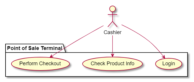
One tool often used in software documentation is UML or Unified Modeling Language. UML is a standard way of visualizing software systems, offering a variety of diagram components which can be used to describe a multitude of software behavior or structure. UML diagrams allow developers to communicate system designs in a visual manner such as the one shown below for a Point of Sale Terminal system:

Making UML Diagrams in Visual Studio Code
You can make UML diagrams in a textual manner. This makes the diagram easier manage and storable in version control. This can be done in Visual Studio Code with the help of a pretty cool extension - Markdown Preview Enhanced and a powerful UML library PlantUML.
Installing Requirements
First, install the extension in Visual Studio Code - open the Extensions tab, and search and download Markdown Preview Enhanced by Yiyi Wang in the marketplace.
Second, to be able to work with PlantUML, download and install Java and Graphviz by clicking on the respective links.
Once these are setup, you should be able to start writing UML diagram in Visual Studio Code.
Writing with PlantUML
Different kinds of UML diagrams can be written with PlantUML. For now, we are just going to make a Use Case Diagram to demonstrate this capability. We’ll try to create the Point of Sale Terminal use case diagram shown earlier.
-
Start with the following lines to tell the markdown renderer that we are trying to create a PlantUML diagram.
``` puml ``` -
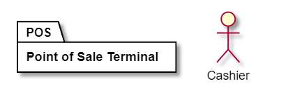
Define the components that will be part of the diagram - the Cashier actor and the POS component.
 ``` puml

 actor Cashier

 package POS as "Point of Sale Terminal" {
 }

 ```
-
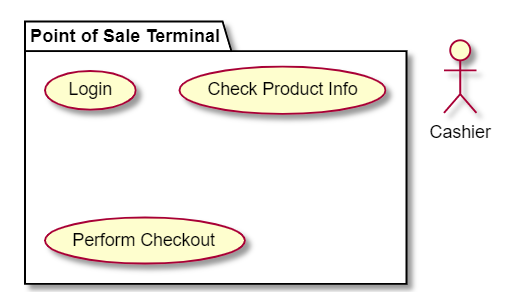
POS also has some use cases which we shall define inside the POS package.
 ``` puml

 actor Cashier

 package POS as "Point of Sale Terminal" {
     usecase Login
     usecase CheckProduct as "Check Product Info"
     usecase PerformCheckout as "Perform Checkout"
 }

 ```
-
Next, we connect the Cashier to each of the POS use case.
 ``` puml

 actor Cashier

 package POS as "Point of Sale Terminal" {
     usecase Login
     usecase CheckProduct as "Check Product Info"
     usecase PerformCheckout as "Perform Checkout"
 }

 Cashier --> Login
 Cashier --> CheckProduct
 Cashier --> PerformCheckout

 ```
-
Lastly, we arrange the components from left to right to make it a bit more visually appealing.
 ``` puml

 left to right direction

 actor Cashier

 package POS as "Point of Sale Terminal" {
     usecase Login
     usecase CheckProduct as "Check Product Info"
     usecase PerformCheckout as "Perform Checkout"
 }

 Cashier --> Login
 Cashier --> CheckProduct
 Cashier --> PerformCheckout

 ```
The Use Case Diagram is only one of the many UML diagrams that can be used to describe a software system. Activity Diagrams, Sequence Diagrams, Class Diagrams and a lot more can be made and are fully documented in PlantUML’s website.
Conclusion
UML diagrams can be useful in scenarios where it can be an effective communication tool. It can be used in the system design phase, in on-going documentation, or simply when describing a software system to clients.
Do be wary of over-documentation. Not every corner of your system has to be comprehensively documented. This may only lead to additional work and maintenance which does more harm than good.
In the words of Martin Fowler:
Remember that the code is the repository of detailed information, the diagrams act to summarize and highlight important issues.